high-voltage-pulse-generator
General Schematic
The circuit is divided into 7 sections detailed below:
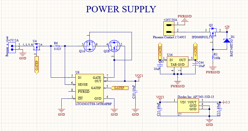
1. Power Supply
Different protection circuits (overvoltage/overcurrent and reverse voltage protection) are included for both power supplies, and fixed voltage regulators of 3.3V and 12V are also added.
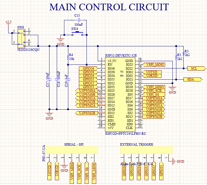
2. Main Control Circuit
Pinout of ESP32-DEVKITC-32E. Includes PWM signals: UxPWMXA, UxPWMXB (different units and operators), SPI and SERIAL connectivity, External Trigger, I2C protocol (SDA, SCL), Switch SW6 which allows the microcontroller to be powered from an external source or from the ESP32 serial port.
!! Warning !! !! While you have the ESP32 serial port communication connected, you cannot enable the power supply from the external source.
3. Digital Potentiometer
Pinout of ESP32-DEVKITC-32E. Includes PWM signals: UxPWMXA, UxPWMXB (different units and operators), SPI and SERIAL connectivity, External Trigger, I2C protocol (SDA, SCL), Switch SW6 which allows the microcontroller to be powered from an external source or from the ESP32 serial port.

| CHIP | PORT | CHANNEL HVPG |
|---|---|---|
| CHIP1_ADDR (U1) | P3W, P3B | CH1 |
| CHIP3_ADDRU0 (U3) | P1W, P1B | CH2 |
| CHIP3_ADDRU0 (U3) | P2W, P2B | CH3 |
| CHIP1_ADDRU1 (U1) | P1W, P1B | CH4 |
| CHIP2_ADDR (U2) | P3W, P3B | CH5 |
| CHIP2_ADDRU1 (U2) | P2W, P2B | CH6 |
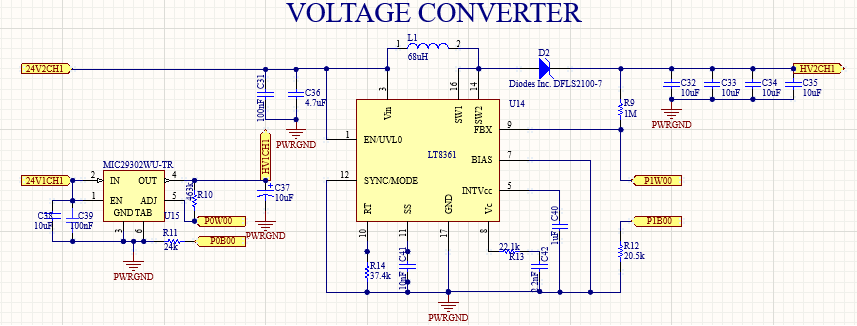
4. Voltage Converter
Two converters for voltage control in the primary of the transformer were included whose specifications are as follows:
| CHIP | CONVERTER | INPUT VOLTAGE | OUTPUT VOLTAGE |
|---|---|---|---|
| MIC29302 | LINEAL | 24V | 12-24V |
| LT8361 | BOOST | 24V | 24-80V |
i Note i i Both converters can be controlled from the digital potentiometer outputs, as the resistance of the voltage divider (signal control feedback) can increased or decreased. The LT8361 converter is not recommended as it has issues working with an inductive load. Nevertheless, the functionality of this circuit is not necessary for the proper operation of the high-voltage pulse generator.
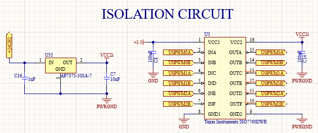
5. Isolation Circuit
The ISO7760 isolation circuit is included to prevent distortion of the PWM signals from the ESP32 due to noise from the inverter’s switching on the power ground.
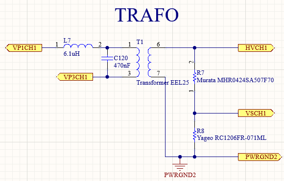
6. High Frequency Transformer
The high-frequency transformer model EEL25 is connected to each channel of the high-voltage pulse generator as follows:
• VP1CH1 and VP3CH1 are the outputs of each inverter.
• HVCH1 is the high-voltage sinusoidal waveform of each channel.
• VSCH1 is the monitoring voltage, which is 500 times lower than the high voltage.
• PWRGND2 is the high voltage ground common to all channels.
! Caution ! ! Since the high voltage ground is common across all channels, there could be current returns that cause voltage coupling between different channels. After the tests performed, these differences remain within a safe operating range. However, you should consider these variations if you need all channels to operate at the same voltage level; in that case, you should set the digital potentiometers at different levels.
7. Isolated Amplifier
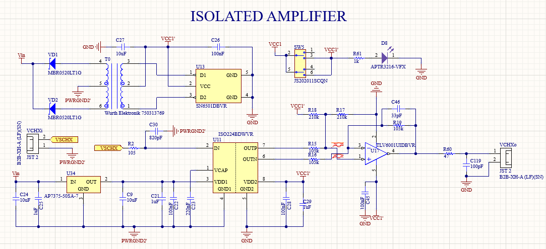
An isolated amplifier is included for high-voltage monitoring to prevent damage to the oscilloscope or ADC used.
i Note i i You may omit this circuit at your own risk.
