high-voltage-pulse-generator
High Voltage Pulse Generator Assembly
For the routing and assembly of the PCB, refer to the instructions specified in the previous section. Attached are the Gerber Files and the BOM_Control materials list for you to send to your suppliers.

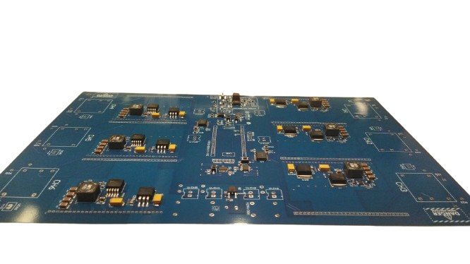
HVPG Asembly
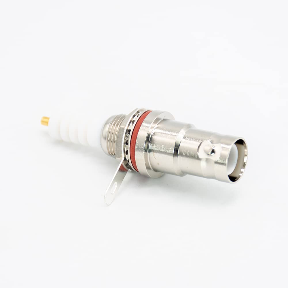
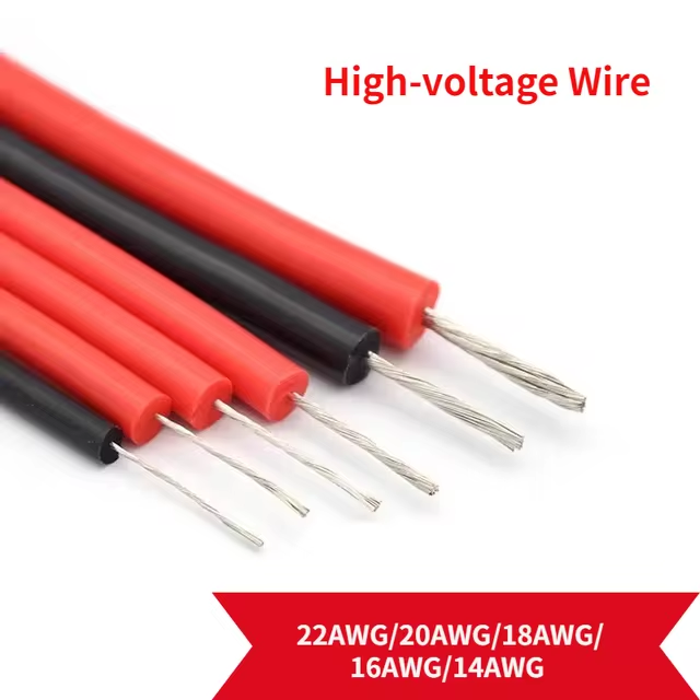
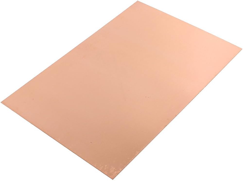
For final assembly, it is recommended to have the following supplies and equipment: SHV panel connector, cable SHV 5KV 1[m] , cable high voltage 2[m], flux off, plastik, FR4 board 330x215 [mm], M3X20 [mm] spacers, M3 allen key, M3 hex nuts, welding station.



Follow these steps for manufacturing:
1.- Design and 3D print a panel for the 7 SHV connectors, with a height of 20mm to keep the control PCB and the FR4 plate (PWRGND2) separated.
2.- Solder the high-voltage output from the secondary of the transformer HVCHx to the core of the SHV connector for 6 channels. Solder PWRGND2 to 1 SHV connector for work like common power ground.
! Caution ! Apply flux off at solder points to avoid undesirable impedances in high-voltage lines. Apply Plastik (dielectric thickness) at high-voltage points that are close to lower voltage lines. The SHV connector panel must be grounded to PWRGND2.
3.- To insert the common power ground, follow these steps:
• Make 8 holes in the FR4 board, 4 at each end in the following positions (x,y)[mm]: {(10,320), (80,320), (145,320), (205,320); (10,10), (70,10), (135,10), (205,10)}
• Position the M3X20mm spacers on the control PCB that is coupled to the panel with the SHV connectors
• Insert the FR4 board at the other end of the SHV panel
• Tighten both boards with M3 nuts and flip the multi channel HVPG board.
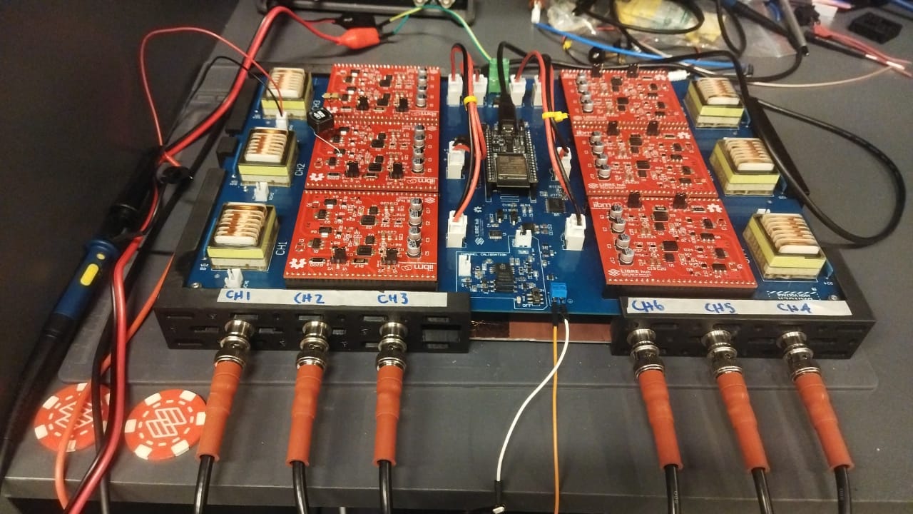
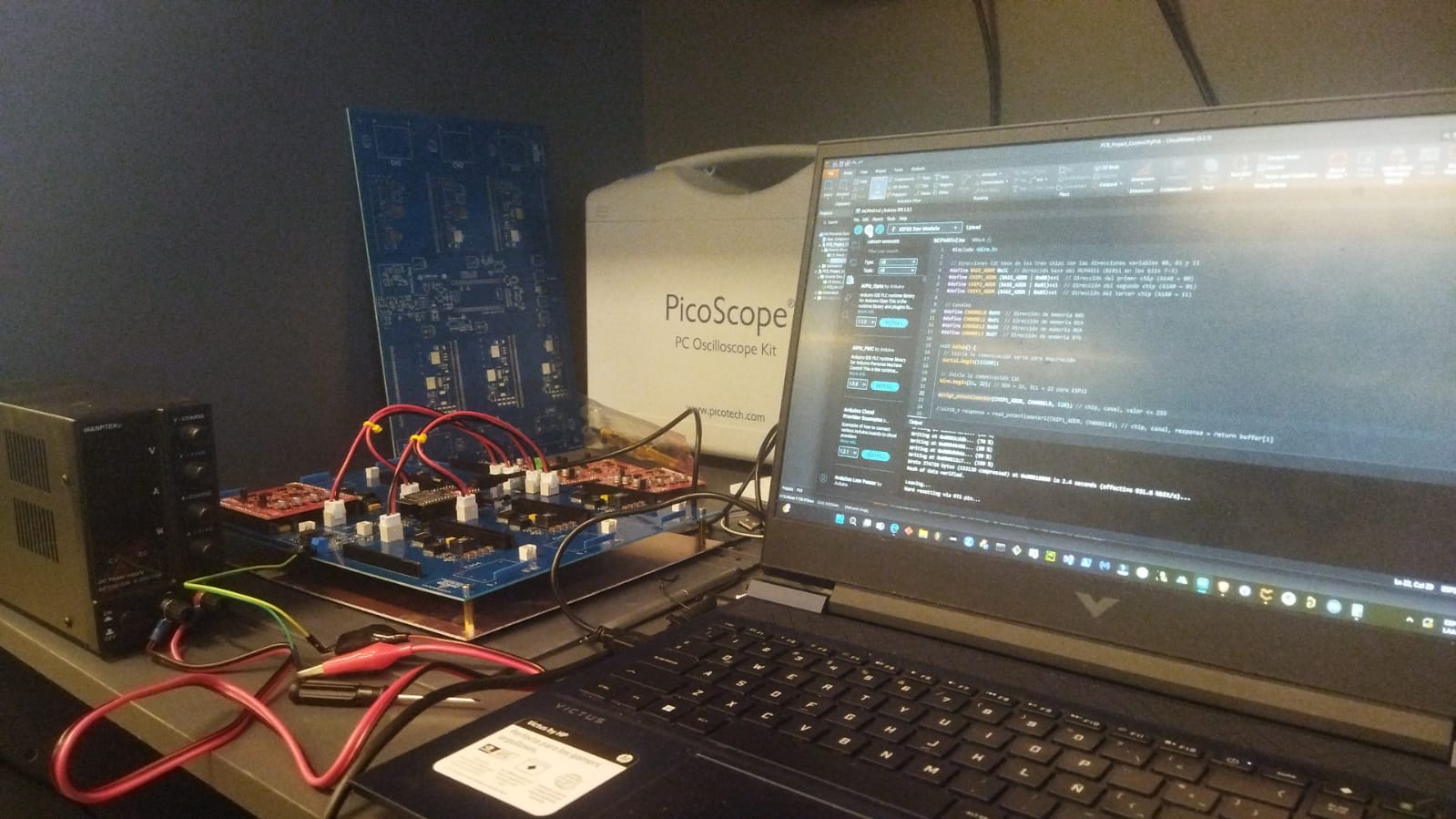
!! Warning !! !! The spacers in the positions (10,10) and (205,320) [mm] should not do contact with power ground. Apply Plastik (dielectric thickness) and remove the copper in this positions of FR4 board.
4.- Inspect the multi channel HVPG board for any defects. Use a tester to check for short circuits between VCC, HV and ground to avoid damaging the circuit before performing functionality tests.