high-voltage-pulse-generator
PWM Signals
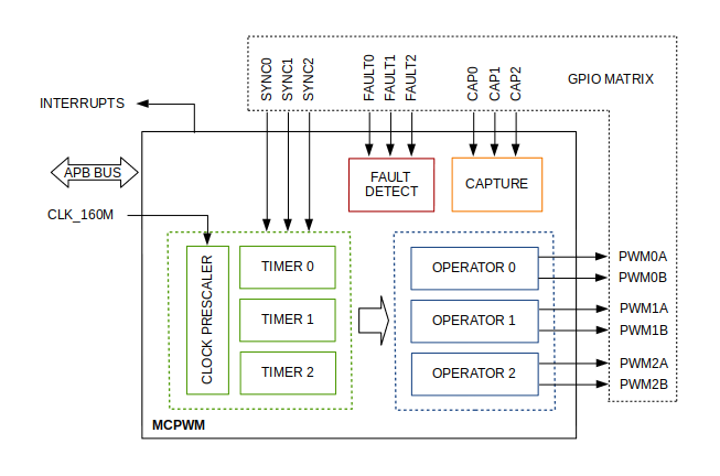
To generate the PWM signals, it is recommended to use the functionalities of Motor Control Pulse Width Modulation (MCPWM) library in your ESP32 project. This library provides the functions and definitions needed to control and manage PWM signals, which are especially useful for a Full Bridge Single-Phase Inverter. The driver/mcpwm.h header file is part of the ESP-IDF Espressif IoT Development Framework and contains the declarations for the MCPWM functions and data structures. The architecture and some of its main functionalities are as follows:

• It has two units, each unit has three PWM output pairs.
• Each output A / B pair can be synchronized with one of three synchronization timers 0, 1, or 2.
• Each unit is also capable of collecting input signals as SYNCHRONIZATION SIGNS;
The ESP32 ports that output PWM signals to each channel of the high-voltage pulse generator are as follows.
| UNIT | OPERATOR | CHANNEL | GPIOs (A, B) |
|---|---|---|---|
| U0 | 0 | CH1 | 17, 16 |
| U0 | 1 | CH2 | 4, 0 |
| U0 | 2 | CH3 | 2, 15 |
| U1 | 0 | CH4 | 25, 26 |
| U1 | 1 | CH5 | 27, 14 |
| U1 | 2 | CH6 | 12, 13 |
Here is the function that generates the PWM signal for each channel:
void mcpwm(mcpwm_unit_t Unidade,
           mcpwm_io_signals_t Operador_A,
           mcpwm_io_signals_t Operador_B,
           mcpwm_timer_t TIMER,
           int GPIO_A,
           int GPIO_B,
           int freq) {
// Function implementation
}
An example of how to use it from void setup() to generate a PWM signal on channel 1, considering that you should define the frequency as an integer between 80-100 kHz:
i Note i i If you use the amplifier circuit version with the LC filter incorporated in each channel of the high-voltage pulse generator, you can operate at lower frequencies down to 50 kHz without distorting the sinusoidal signal.
mcpwm(MCPWM_UNIT_0, MCPWM0A, MCPWM0B, MCPWM_TIMER_0, GPIO_U0_PWM0A_OUT, GPIO_U0_PWM0B_OUT, Frequency); //CH1
! Caution ! !If you increase or decrease the PWM frequency outside the range of 80-100 kHz, the maximum voltage of the respective channel will significantly decrease. You can monitor this effect with an oscilloscope, ensuring that you measure with a 10 MΩ impedance to avoid affecting the impedance of the voltage divider in the secondary transformer. Note that the measured voltage is 500 times lower than the high voltage.