high-voltage-pulse-generator
Digital Potentiometer
The digital potentiometer MCP4451(I2C protocol) was programmed to remotely control the voltage level of each channel of the high voltage pulse generator. The following section explains its main functions, allowing for eventual modifications, communication with other devices, and/or the development of a user interface.
For modifying the functions, consider that each channel is assigned the following memory address.
| CHANNEL | ADDRESS |
|---|---|
| CH 1 | CHIP1_ADDR, CHANNEL3 |
| CH 2 | CHIP3_ADDR, CHANNEL1 |
| CH 3 | CHIP3_ADDR, CHANNEL2 |
| CH 4 | CHIP1_ADDR, CHANNEL1 |
| CH 5 | CHIP2_ADDR, CHANNEL3 |
| CH 6 | CHIP2_ADDR, CHANNEL2 |
Functions
1.- To write to a specific position on the digital potentiometer, the following data structure is considered.

With this in mind, the following function is defined, allowing the assignment of a value between 0-255 (8 bits) to each channel of each chip.
void assign_potentiometer(uint8_t chipAddr, uint8_t channel, uint8_t set_value) {
    // Function implementation
}
Example: assign_potentiometer(CHIP1_ADDR, CHANNEL3, 0); // chip, canal, 0 < valor <= 255
! Caution ! Note that a value of 0 assigns the maximum voltage, and 255 corresponds to the minimum voltage output from each channel of the high voltage pulse generator.
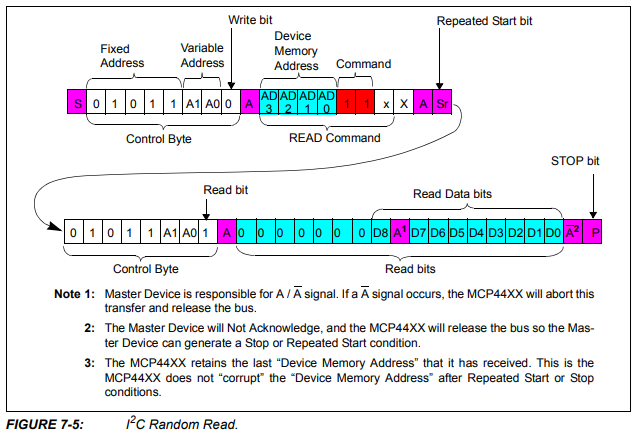
2.- To read to a specific position on the digital potentiometer, the following data structure is considered.

The function that returns the assigned value for each channel and chip is:
uint8_t read_potentiometer2(uint8_t chipAddr, uint8_t channel) {
    // Function implementation
}
Example: read_potentiometer2(CHIP2_ADDR, CHANNEL3) // chip, canal, response2 = return lowByte of Channel 5
i Note i Add a delay(1000) before calling the read_potentiometer2(uint8_t chipAddr, uint8_t channel) function from void setup().
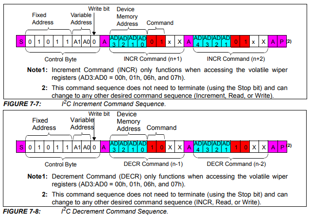
3.- To continuously increase and decrease the position of the digital potentiometer, the following specific functions are implemented according to the data structure specified by the manufacturer.

void incrementPotentiometer(uint8_t chipAddr, uint8_t channel) {
    // Function implementation
}
void decrementPotentiometer(uint8_t chipAddr, uint8_t channel) {
    // Function implementation
}
These functions were implemented to characterize each channel of the high-voltage pulse generator. For example, the following function allows varying the voltage of each channel from a maximum voltage (pos_init=0) to a minimum voltage. The idea is to record this with an ADC and/or oscilloscope to document the operating voltage range of each channel of the equipment.
void calibration_Range1() { // simultaneous calibration of 2 channels at a time
  // List of chips and channels to characterize: CHIP2-CHANNEL3 is channel 5, CHIP2-CHANNEL2 is channel 6
  uint8_t chips[] = {CHIP2_ADDR}; // CHIP1_ADDR, CHIP2_ADDR, CHIP3_ADDR
  uint8_t channels[] = {CHANNEL2, CHANNEL3}; // CHANNEL1, CHANNEL2, CHANNEL3
  uint8_t pos_init = 0;
  // Increment the initial position of the potentiometers in each chip and each channel
  for (uint8_t i = 0; i < sizeof(chips) / sizeof(chips[0]); i++) {
    for (uint8_t j = 0; j < sizeof(channels) / sizeof(channels[0]); j++) {
      assign_potentiometer(chips[i], channels[j], pos_init); // start sweeping from position pos_init
      for (uint8_t k = 0; k < 255 - pos_init; k++) {
        incrementPotentiometer(chips[i], channels[j]); // increments the position of the potentiometer varying from maximum to minimum voltage
        delay(1000);
      }
    }
  }
}
i Note i If you prefer, you can vary the position continuously from a minimum to a maximum voltage using the decrement function instead of increment.